
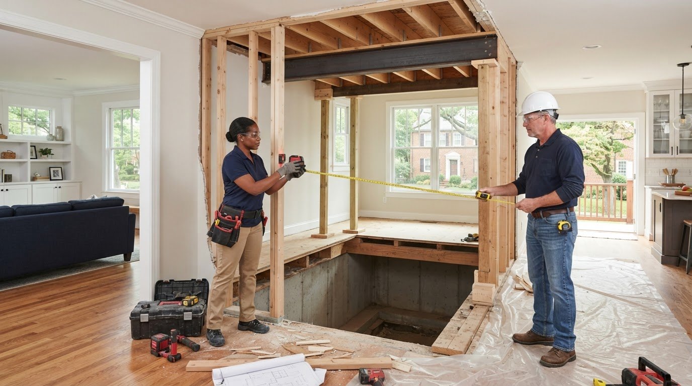
How to Plan Structural Wall Removal When Joists Run Parallel
Parallel second-floor joists often indicate that a wall isn’t supporting their load, but they don’t prove it is non-load-bearing. Structural wall removal when second-floor joists run parallel to the wall still requires checking whether doubled ceiling joists rest on it or nearby framing transfers weight to it. A load-bearing wall supports weight that must be redirected through a properly sized beam and its end supports.
It’s understandable to see joists running the other way and assume the wall can come out. What matters is what the framing supports: a non-load-bearing wall doesn’t carry the structure above, while a load-bearing wall forms part of the home’s load path. Assess the ceiling framing, look for doubled joists, plan suitable beam supports, and account for utilities before work begins.
Key Takeaways
- Trace the load path from the framing above the wall through its end supports and down to the foundation before planning removal.
- Allow for at least 3 inches of support at each beam end in ideal circumstances, using properly planned jack or trimmer studs.
- Look for doubled ceiling joists resting on the wall; joists running parallel don’t rule out a load-bearing role.
- Check nearby framing carefully: a wall parallel to and within 2 or 3 feet of a joist may still carry load.
- Plan access for framing and utilities; removing the wall may require opening 1-2 feet of ceiling on either side.
Beam end supports and load paths
The project price depends on factors such as the beam span and load, access, temporary support, and finish repairs. Removing a load-bearing wall requires a replacement header or beam designed to carry its load.
- Trace the load path before planning the opening. A load-bearing wall transfers ceiling weight to a wall or post below, then down to the basement foundation or column footings. Follow the framing above the proposed opening and identify where its weight currently lands. For example, note whether the wall continues below or aligns with a post. A beam must redirect that load to suitable supports at both ends.
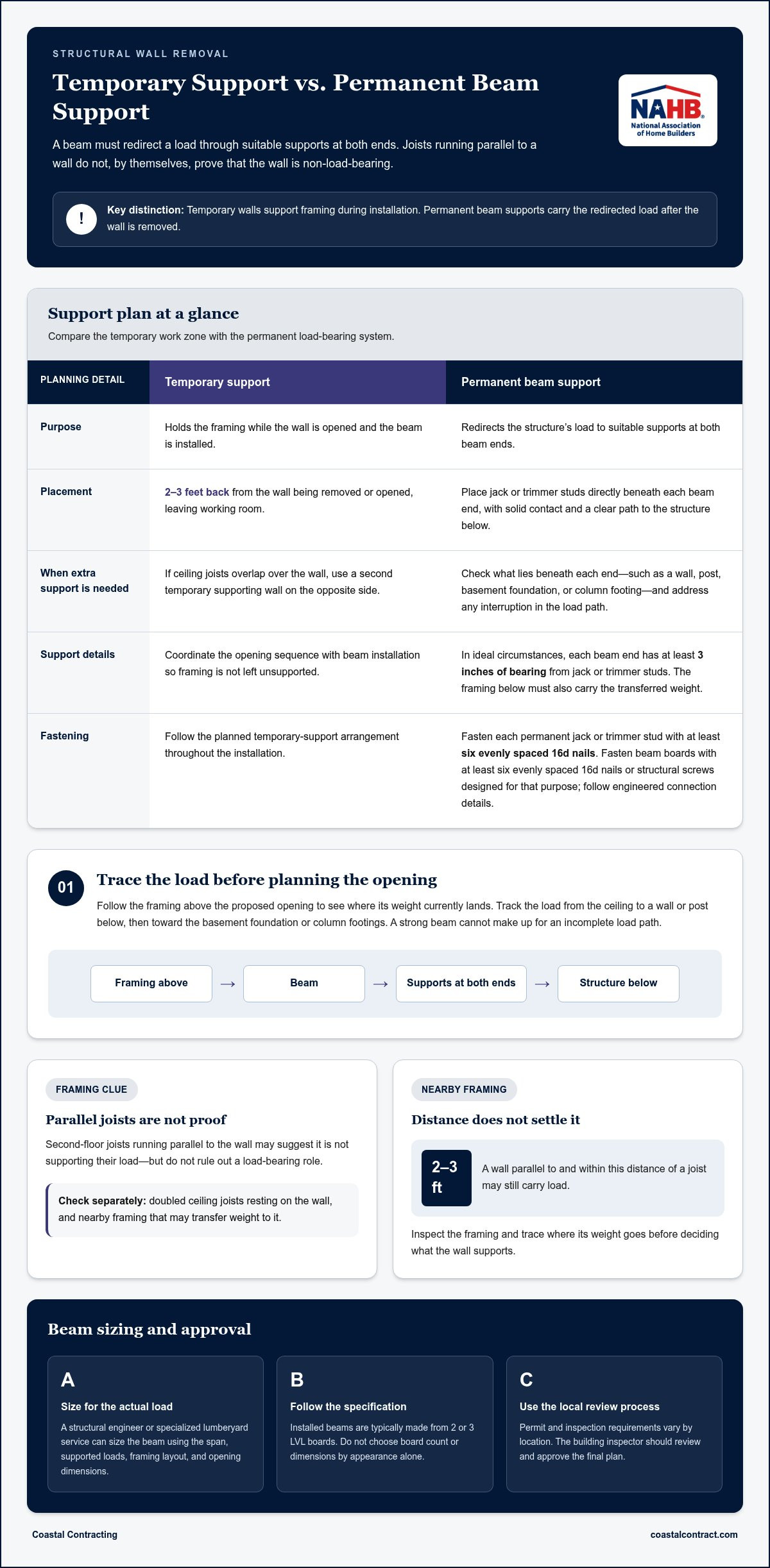
- Identify what each beam end will rest on. The beam’s support must connect its load to framing below, rather than stopping at unsupported floor sheathing. In ideal circumstances, each end has at least 3 inches of support from jack or trimmer studs. That measurement describes bearing at the beam end, not the overall size of the support assembly. The framing below must also carry the transferred weight.
- Plan temporary support before opening the wall. A temporary supporting wall should sit 2-3 feet back from the wall being removed or opened. This creates working room while supporting the framing during installation. If ceiling joists overlap over the wall, use a second temporary supporting wall on the opposite side. Keep the opening sequence coordinated with the beam installation so framing isn’t left unsupported.
- Match the permanent supports to the beam layout. Place the jack or trimmer studs directly beneath each beam end, with solid contact and a clear path to the structure below. Fasten each permanent jack or trimmer stud with at least six evenly spaced 16d nails. Beam boards should be fastened to framing with at least six evenly spaced 16d nails or structural screws designed for that purpose. Follow the engineered connection details.
- Check the full route beneath both supports before removing wall framing. A post or wall below may carry load toward the basement foundation, while a column footing provides another route. Look for interruptions, such as an opening or framing that doesn’t line up with the proposed support. Record what sits beneath each beam end, then make sure the support plan addresses both locations. A strong beam cannot compensate for an incomplete load path.
There is no fixed price; the cost is determined after a quote request. It depends on factors such as the beam span and load, access, temporary support, and finish repairs.
Beam sizing and approval
Choose the beam based on the loads and opening, not joist direction alone. A structural engineer or specialized lumberyard service can size it. The building inspector should review and approve the final plan.
Determine Beam Size
Bring the framing layout and proposed opening dimensions to a structural engineer or specialized lumberyard service. They need to account for the span, supported loads, and how the beam ends connect to their supports. Installed beams are typically made from 2 or 3 LVL boards. Don’t select board count or beam dimensions by appearance alone; the project’s load and framing details drive sizing.
Check Local Code and Permit Rules
Contact the local building department to learn which permit and inspection steps apply to your address. Requirements vary by location, so the process in one community may not match another’s. There isn’t one nationwide checklist for every home: follow local instructions and submit the structural plan for review. The building inspector should review and approve the final plan.
- Document the proposed opening before requesting beam sizing. Record its location and span, then show how the second-floor framing relates to the wall. Include framing details that affect the beam’s load. A clear drawing gives the engineer or specialized lumberyard service the information needed to assess the design, rather than guess from joist direction alone.
- Ask for a beam specification that matches the actual framing. The design should identify the beam materials and dimensions, along with how its components connect. If the recommendation uses 2 or 3 LVL boards, follow the specified arrangement and fastening details. Substituting a different board count or changing the connection can alter how the beam performs.
- Submit the structural plan through the local permit process before beginning removal. Follow the building department’s instructions for documents and inspections. Keep the approved plan on site, then make sure the installed beam and supports match its details. Review and approval of the final plan are key project checkpoints.
- Keep approval aligned with the construction sequence. Plan beam installation around the approved design, including its specified supports and connections. If the framing exposed during work differs from the drawing, pause before making design changes. A revised beam or support detail can affect the plan, so resolve discrepancies through the appropriate review process before covering the work.
Checking for doubled ceiling joists
Parallel second-floor joists don’t establish whether a wall carries load. For structural wall removal when second-floor joists run parallel to the wall, inspect ceiling framing separately. A doubled ceiling joist resting on the wall can make it load-bearing.
- Locate ceiling joists above the wall and trace their direction and endpoints. Use an attic or exposed framing, where available, to see whether each joist ends, overlaps, or continues across the wall. A finished ceiling can conceal those details, so don’t treat the visible surface as evidence of the framing layout. Record what you can see before assessing the wall’s role.
- Look for two ceiling joists fastened together above the wall. A wall parallel to the ceiling joists may still be load-bearing if a doubled ceiling joist rests on it. Check that both members actually bear on the wall. Two nearby boards don’t necessarily form a doubled member, and their position matters as much as their appearance.
- Trace any paired joists along their length and note where they meet other framing. For example, a doubled ceiling joist resting on the wall may transfer weight there even though the second-floor joists run parallel. Compare the visible framing on both sides and record overlaps and bearing points. These observations help clarify how the ceiling framing is supported.
- Keep ceiling framing and second-floor joists distinct in your notes. Label their directions separately, then mark any doubled ceiling joists and where they contact the wall. This avoids confusing the floor-joist layout with a separate ceiling load. During structural wall removal when second-floor joists run parallel to the wall, that distinction can reveal a load-bearing condition missed by looking at floor joists alone.
- Use the framing evidence to guide the structural assessment, not as permission to remove the wall. Share the layout, doubled members, and bearing locations with the professional sizing the replacement beam. If the ceiling hides a connection, expose the framing before finalizing the plan. A clear sketch of the wall and joists helps explain the condition and supports a sound decision.
Exceptions when joists run parallel to a wall
Parallel joists don’t rule out a wall’s structural role. Check nearby framing and arrange temporary support before opening or removing the wall.
Identify Exceptions to Parallel Joist Patterns
Map the wall against the framing, then look for load paths that joist direction alone won’t reveal. A wall parallel to and within 2 or 3 feet of a joist may still be load-bearing. Also note whether the wall runs parallel to the roof ridge or sits directly above a basement beam, since both are typical indicators of a bearing role.
- Measure the wall’s position relative to the nearest joist and record the relationship on a simple framing sketch. If the parallel wall lies within 2 or 3 feet of that joist, don’t assume it is non-load-bearing. Include the joist’s direction and the wall’s location so the structural assessment reflects their actual layout.
- Compare the wall’s position with the roof ridge and framing below. A wall parallel to the roof ridge is a typical load-bearing indicator. A wall directly above a basement beam is typically load-bearing. Note either alignment on your sketch, then consider those clues alongside joist spacing and bearing points.
Set Up Temporary Shoring
Build temporary support before removing or opening a wall that carries framing. Place a temporary supporting wall 2-3 feet back from the wall being opened. If ceiling joists overlap over the wall, use a second temporary supporting wall on the opposite side. These supports hold framing while the permanent beam and its supports are installed.
- Mark the temporary wall’s position 2-3 feet from the opening, leaving room to work along the original wall. Keep the support parallel to the wall being opened so it can support the framing across the work area. The temporary wall is part of the removal sequence, not a substitute for the planned permanent beam.
- Check the ceiling joists for an overlap above the wall before beginning removal. When they overlap, place a second temporary supporting wall on the opposite side. This arrangement supports framing from both sides during the work. Don’t proceed with the opening until the temporary supports are in place.
- Keep the temporary supports in position while the wall is opened and the permanent beam is installed. The temporary walls support framing during that transition; the beam and its end supports provide the planned permanent load path. Remove temporary supports only after the permanent support is ready.
Exposing framing and relocating utilities
Inspect attic and basement framing by tracing joists above the wall and supports below it. Access may require opening 1-2 feet of ceiling on either side to expose framing and relocate utilities.
Expose Framing
Open the ceiling around the proposed wall carefully, allowing access to framing and any utilities crossing the work area. An opening of 1-2 feet on either side may be needed. Note the location of visible pipes, wiring, and other services before planning changes, so the beam installation can account for them.
Inspect Attic and Basement Framing
Trace the framing above the wall in the attic, then follow its support below in the basement. Look for joists, doubled members, posts, and beams that align with the wall. For example, a basement beam directly below can help reveal where loads travel. Record these connections for the structural plan.
- Mark the wall’s position on a simple sketch before opening the ceiling. Include the direction of the second-floor joists and the proposed opening, then update the sketch as framing becomes visible.
- Expose enough ceiling to see framing at the wall and along both sides. An opening of 1-2 feet on either side may provide access for inspection and utility relocation.
- Identify utilities crossing the planned opening, including visible wiring and pipes. Mark where each enters and exits the wall area so the work plan accounts for routes that may need relocation.
- Inspect the attic framing above the wall. Trace joists to their bearing points and note any doubled ceiling joists resting on the wall. These details help show how framing transfers weight.
- Look beneath the wall in the basement for a supporting wall, post, or beam. Record whether a basement beam aligns with the wall, since that relationship can indicate a load path.
- Compare the attic and basement observations. For example, joists bearing above and a beam below may show how loads travel through the home. Add both findings to the same sketch.
- Plan utility relocation alongside the beam work. Keep exposed routes visible in the project notes, and don’t cover the framing before the structural plan and utility changes are coordinated.
If your project includes attic or basement remodeling, plan framing access and utility routes as part of the wider renovation.
Coastal Contracting: General Contracting
Coastal Contracting provides general contracting for remodeling projects involving significant changes to your home. If wall removal is part of an interior remodel or home addition, coordinate it with the wider project plan, including the beam, supports, and affected finishes.
Bring your goals and the structural information you’ve gathered to the planning conversation. Coastal Contracting provides general contracting and interior remodeling, keeping the wider scope in view as your renovation takes shape. If your project adds space, a home addition may also be relevant.
Visit coastalcontract.com to discuss your remodeling project with Coastal Contracting.
Plan the next phase with confidence
Structural wall removal when second-floor joists run parallel to the wall is part of a larger home decision: how the updated space should work for you. Before construction begins, consider how the opening connects to circulation, storage, natural light, and future improvements. Coordinating the project can make the new layout feel intentional rather than like an isolated change.
Coastal Contracting provides general contracting for projects that bring multiple parts of a home renovation together. If your plans include expanding the footprint, a home addition may fit; exterior remodeling can address related changes outside. The right scope depends on the result you want, so outline your priorities and questions before moving forward.
Discuss your project with Coastal Contracting and explore a thoughtful path from your current layout to a home that better suits your needs.
Frequently Asked Questions
What’s the Difference Load and Non-Load Bearing?
A load-bearing wall supports structural weight and transfers it to framing or foundations below; a non-load-bearing wall primarily divides spaces. The distinction matters because removing the first changes how the home carries weight, while removing the second doesn’t redirect that structural load. A partition may still contain wiring or plumbing, so its structural role and utility contents are separate questions to resolve.
Will the New Beam Be Flush or Protrude Down?
The beam may be flush with the ceiling framing or extend below it, depending on the structural design and available space. A flush installation needs room within the framing depth and suitable connections; a beam below the ceiling may be needed when that space isn’t available. Existing ducts, pipes, and wiring can also affect placement. Review the beam position in the plans before choosing ceiling finishes.
Does a wall support the second floor if joists run parallel to it?
Usually, the second-floor joists alone don’t establish that the wall carries load, but parallel joists don’t prove it is non-load-bearing. Separate ceiling framing, doubled members, or nearby supports may still transfer weight to the wall. For example, a wall can support doubled ceiling joists even when the floor joists run alongside it. Assess the complete framing arrangement rather than judging the wall by one joist direction.
What framing conditions make a parallel wall load-bearing, such as joist splices or blocking?
A parallel wall may carry load if doubled ceiling joists rest on it or nearby framing transfers weight to it. Joist splices or blocking deserve careful inspection because their position and connections affect how loads travel; their presence alone doesn’t establish the wall’s role. Note whether members bear on the wall, connect across it, or align with supports below, and include those details in the framing assessment.
What beam size is needed to remove a load-bearing wall under a second floor?
There isn’t one beam size for every opening. The required design depends on the opening’s span, the loads carried above, and the support conditions at each end. A structural engineer or specialized lumberyard service can size the replacement beam using those project details. Two openings of similar width may need different beams if their framing or supported loads differ.
Do I need a structural engineer to remove a load-bearing wall?
Have a structural engineer or specialized lumberyard service size the replacement beam, and have the building inspector review and approve the final plan. These steps address separate needs: sizing matches the beam to the framing, while plan review supports project approval. Permit and inspection requirements vary across Richmond, Henrico, Goochland, Midlothian, Chesterfield, Short Pump, Chester, Glen Allen, Hanover, Ashland, and Montpelier.
What are the risks of removing a wall without confirming its structural role?
Removing a wall that carries framing without a designed replacement can interrupt the home’s load path. The structure may shift, and finishes around the opening can crack or become misaligned. Utilities concealed in the wall or ceiling can also be damaged during demolition. Before work starts, establish the wall’s role and coordinate any beam, support, and utility changes; joist direction alone isn’t enough to make that decision.